Motorsports Data Acquisition (2026)
Every year, Vanderbilt's motorsports team participates in the nation wide Formula SAE automotive competition. Building, testing, and running a brand new motor vehicle against upwards of 80 other universities from around the country.
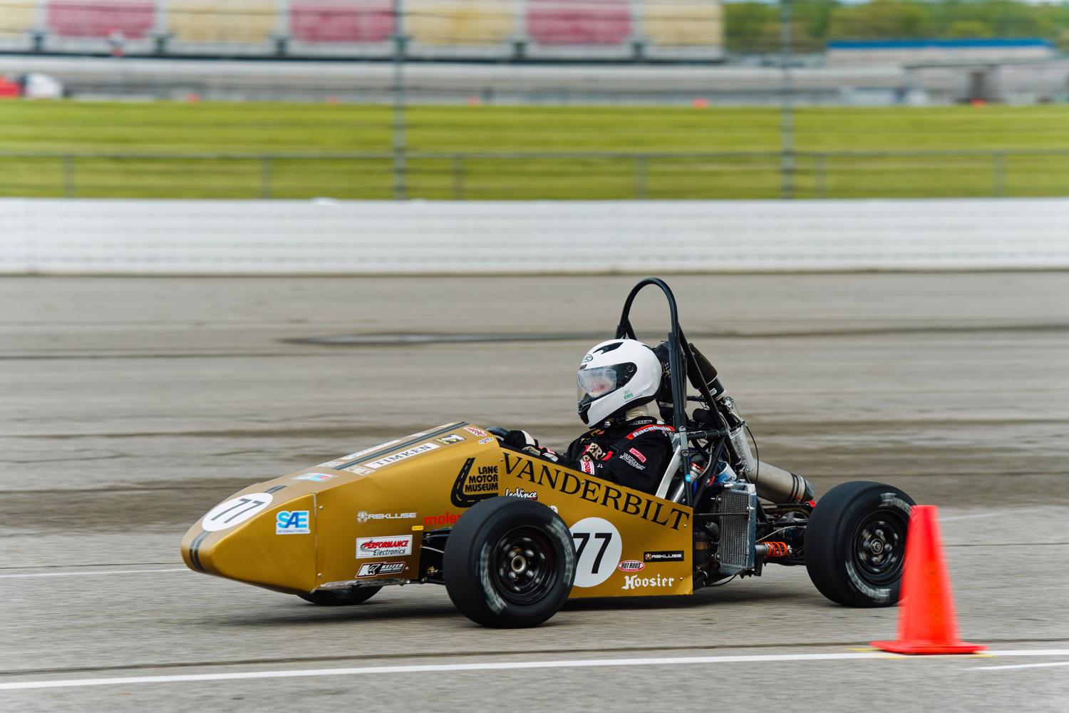
For my capstone graduation project, I helped in the design and implementation of a brand new data acquisition system for their car in the hopes of providing insightful information to aid in any design decisions they may make in future iterations.
My focus was the electrical architecture behind the system: the distributed “nervous system” design, the CAN-based communication pipeline, and the custom gateway PCB that bridges local sensors to the central logging server.
nervous system design
The Motorsports team needed a reliable way to collect data from disconnected sources across the car including vehicle dynamics sensors, cooling system instrumentation, and existing electronics. To solve this, we decided to model the data acquisition network like a nervous system embedded throughout the chassis.
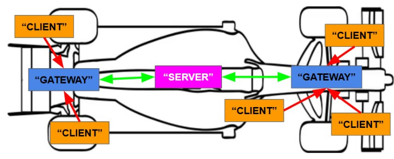
Local sensor clusters connect to nearby gateway boards over short-distance protocols like SPI, I2C, analog inputs, and digital inputs. Those gateways then package the data and forward it across the vehicle over CAN, where the Raspberry Pi timestamps, logs, and prepares the data for analysis.
CAN pipeline
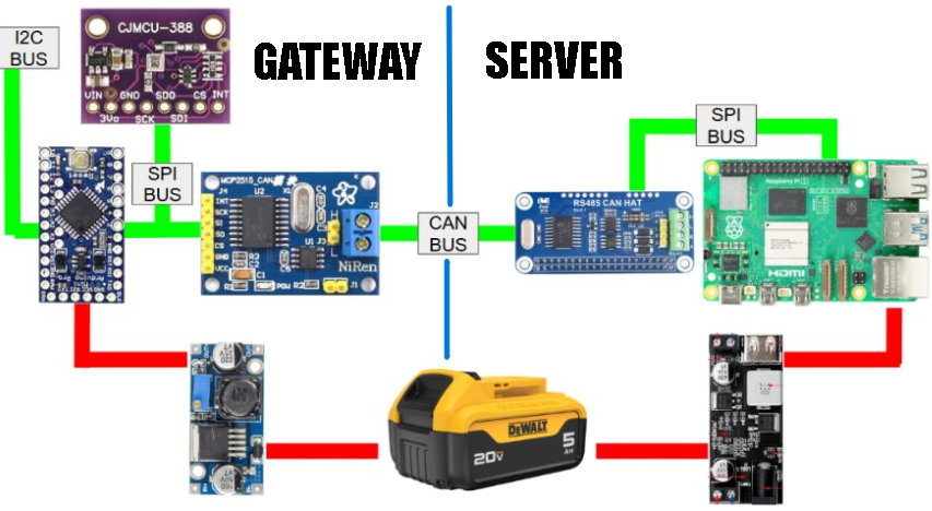
The CAN pipeline was built to make incoming data predictable, timestamped, and easy to expand. Each gateway node uses an Arduino Pro Mini connected to an MCP2515 CAN controller. On the server side, the Raspberry Pi uses a CAN HAT and Python libraries to send startup synchronization frames, receive sensor frames, decode each CAN ID into a named channel, and write the data into CSV files.
To reduce message collisions, the Raspberry Pi sends a startup boot flag to each gateway node. That boot frame assigns a transmit offset and timing window. After receiving its boot flag, each node only transmits during its assigned slot inside the timing cycle. This gives the system a cleaner schedule than having every node broadcast whenever it has data available.
Another advantage of this system is that new sensors can be added by assigning additional gateway inputs, CAN IDs, and software mappings instead of redesigning a completely new infrastructure
gateway PCB
Besides the CAN pipeline, the gateway PCB was my other biggest contribution to the project. The board was designed to be placed near local sensor clusters and act as a compact power, sensor, and communication hub. Each board combines the Arduino Pro Mini, MCP2515 CAN module, buck converter, screw terminals, and labeled interface regions.
The goal was not just to make the circuit work on a bench, but to make it installable and understandable for future Motorsports members. Clear labels, grouped terminals, and a modular layout make the board easier to wire, debug, and reuse when new sensors are added in future seasons.
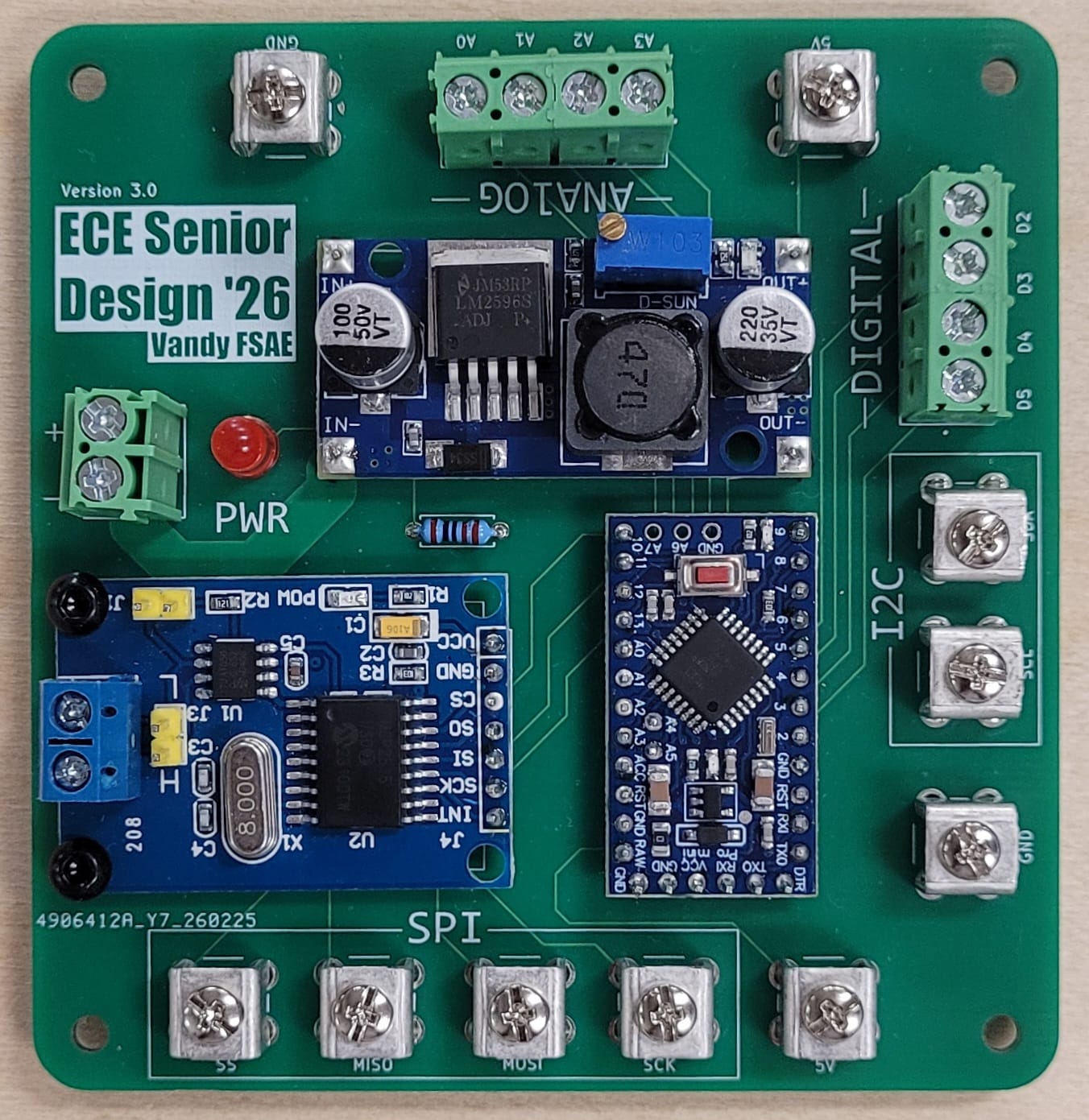
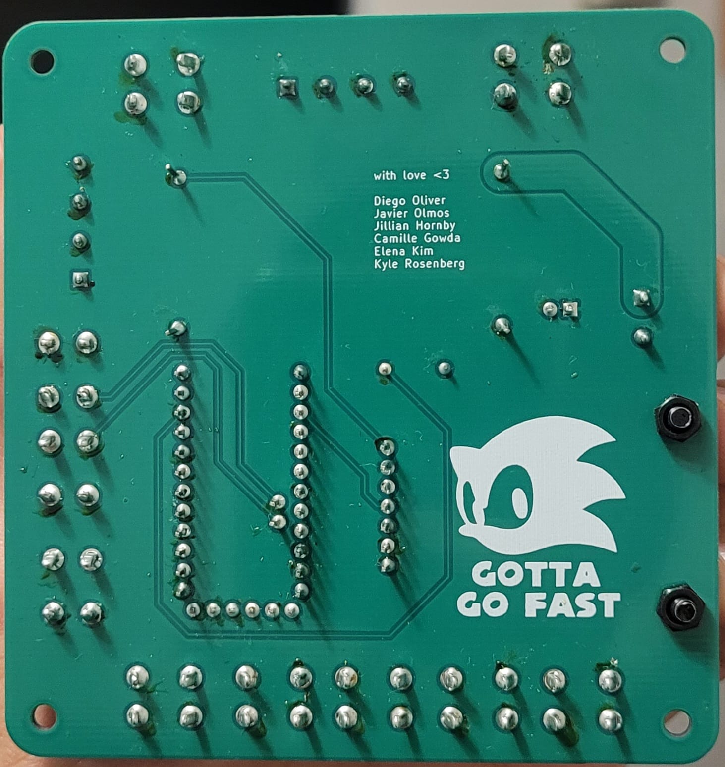
The final PCB emphasized reliability and maintainability. A dedicated ground terminal simplified shared grounding, while a wider battery input trace helped support higher current from the 20 V supply path. The board also separated high-level communication from local sensor wiring, making the gateway a reusable building block instead of a one time prototype.
results
The final prototype demonstrated the full sensor-to-visualization pipeline: gateway nodes collected local data, CAN frames carried synchronized messages to the Raspberry Pi, Python scripts logged the data into structured CSV files, and the visualization software provided an accessible way to inspect vehicle telemetry after a run.
Although full car installation was limited by late arriving sponsor procured components and the vehicle’s own build timeline, the project delivered a validated prototype and documentation package that future Motorsports members can use to complete the final deployment.
The most important outcome was the architecture itself. By building a modular nervous system instead of a fixed sensor bundle, the project gave Vanderbilt Motorsports a foundation that can grow with future cars, new sensors, and new analysis needs.
resources
credits
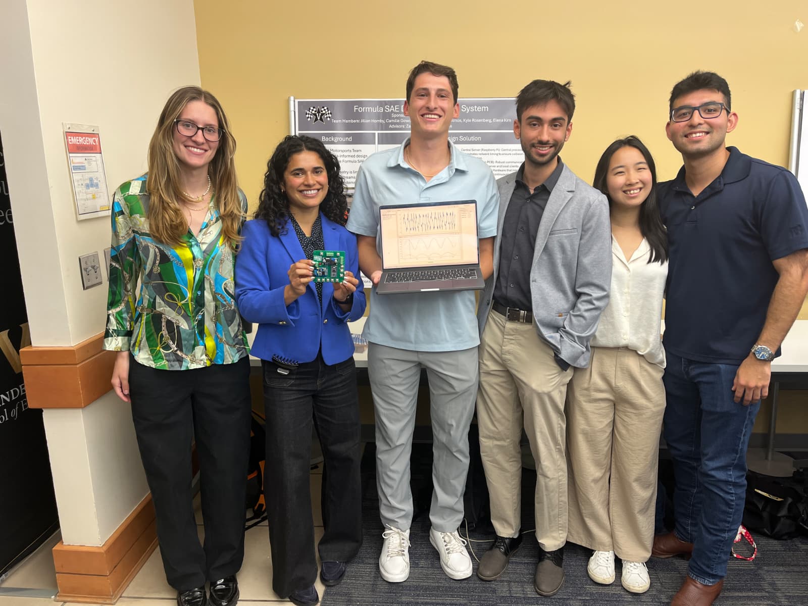
team: Jillian Hornby, Camille Gowda, Diego Oliver, Javier Olmos, Kyle Rosenberg, Elena Kim
sponsor: Vanderbilt Motorsports
advisors: Zachary Martin and Phil Davis